


In Electronics the devices /components which has a specific function with the voltage or current has particular behavior and these devices /components are packed into a protecting envelope by the manufacturer. Each type of package has specific internationally accepted dimensions and materials quality. The subject which deals with those aspects is known as electronic packaging.
PASSIVE COMPONENTS:
A passive component is one that contributes no power gain (amplification) to a circuit or system. It
has no control action and does not require any input other than a signal to perform its function. Since passive components always have gain less than one, they cannot oscillate or amplify a signal. A combination of passive components can multiply a signal by value less than one; they can shift the phase of the signal, reject a signal, but they cannot multiply by more than one because they basically lack gain. Passive devices include resistors, capacitors and inductors etc..
has no control action and does not require any input other than a signal to perform its function. Since passive components always have gain less than one, they cannot oscillate or amplify a signal. A combination of passive components can multiply a signal by value less than one; they can shift the phase of the signal, reject a signal, but they cannot multiply by more than one because they basically lack gain. Passive devices include resistors, capacitors and inductors etc..
RESISTOR:
·A resistor is a two-terminal electronic component that produces a voltage across its terminals that is proportional to the electric current .
·A resistor - an electrical device that resists the flow of electrical current .
The value of a resistor is measured in Ohms and represented by the Greek letter capital omega (Ω).
·A resistor - an electrical device that resists the flow of electrical current .
The value of a resistor is measured in Ohms and represented by the Greek letter capital omega (Ω).
SYMBOL:

Two wires are connected to opposite ends of the resistor. When we apply a potential difference between the wires we set up a current from one wire to the other, through the resistor. The size of the current is proportional to the difference in voltage between the wires. The resistance (in units of Ohms) is defined as the ratio of the applied voltage, V (in Volts), divided by the current, I (in Amps), produced by the applied voltage.
R=V/I

CLASSIFICATION:
Resistors can be broadly of two types.
· Fixed Resistors
· Variable Resistors.
FIXED RESISTORS:
A fixed resistor is one for which the value of its resistance is specified and cannot be varied in general.
RESISTANCE VALUE:
The value of most resistors is shown by a pattern of coloured rings. These are read starting from the band closest to an end.


SMALL VALUE RESISTORS (LESS THAN 10 OHM)
The standard colour code cannot show values of less than 10 . To show these small values two special colours are used for the third band: gold which means × 0.1 and silver which means × 0.01. The first and second bands represent the digits as normal.
For example:
red, violet, gold bands represent 27 × 0.1 = 2.7
green, blue, silver bands represent 56 × 0.01 = 0.56
red, violet, gold bands represent 27 × 0.1 = 2.7
green, blue, silver bands represent 56 × 0.01 = 0.56
RESISTOR TYPES:
All modern resistors can be classified into four broad groups;
- 1. Carbon Composition Resistor - Made of carbon dust or graphite paste, low wattage values
- 2. Film or Cermet Resistor - Made from conductive metal oxide paste, very low wattage values
- 3. Wire-Wound Resistors. - Metallic bodies for heat sink mounting, very high wattage ratings
- 4. Semiconductor Resistors - High frequency/precision surface mount thin film technology
CARBON COMPOSITION RESISTORS (CCR):
Carbon Resistors are the most common type of Composition Resistors as they are a cheap general purpose resistor. Their resistive element is manufactured from a mixture of finely ground carbon dust or graphite (similar to pencil lead) and a non-conducting ceramic (clay) powder to bind it all together. The ratio of carbon to ceramic determines the overall resistive value of the mixture and the higher this ratio is the lower the resistance. The mixture is then moulded into a cylindrical shape and metal wires or leads are attached to each end to provide the electrical connection before being coated with an outer insulating material and colour coded markings.
Carbon Resistor

SPECIFICATIONS:
1. Resistance range - 2.7Ω to 22M Ω
2. Tolerance - ±5 to ±20%
3. Operating temperature - -550 C to 1000 C
4. Power rating - 1/8 to 2w
5. DC working voltage - 150v to 300v
ADVANTAGES OF CCR:
1. Small in size
2. High voltage withstanding capability
3. Low inductance
4. Low capacitance
5. Less cost
6. Long term stability
DISADVANTAGES:
1. Low power rating
2. 1000 C ambience temperature
3. More noise
4. Change in resistance value due to storage
5. high tolerance (upto ±20%)
APPLICATIONS:
Carbon Composite Resistors are low to medium power resistors with low inductance which makes them ideal for high frequency applications but they can also suffer from noise and stability when hot.
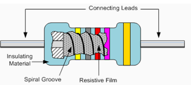
FILM RESISTORS
The generic term "Film Resistor" consist of Metal Film, Carbon Film and Metal Oxide Film resistor types, which are generally made by depositing pure metals, such as nickel, or an oxide film, such as tin-oxide, onto an insulating ceramic rod or substrate. The resistive value of the resistor is controlled by increasing the desired thickness of the film and then by laser cutting a spiral helix groove type pattern into this film. This has the effect of increasing the conductive or resistive path, a bit like taking a long length of straight wire and forming it into a coil.
This method of manufacture allows for much closer tolerance resistors (1% or less) as compared to the simpler carbon composition types. Film type resistors also achieve a much higher maximum ohmic value compared to other types and values in excess of 10MΩ (10 Million Ω´s) are available.
Film Resistor
SPECIFICATIONS:
1. Resistance range - 2.7Ω to 22M Ω
2. Tolerance - ±5 to ±20%
3. Operating temperature - -550 C to 1000 C
4. Power rating - 1/8 to 2w
5. DC working voltage - 150v to 300v
ADVANTAGES
1. Better temperature stability than their carbon equivalents,
2. Lower noise
3. Better for high frequency or radio frequency applications.
4. High surge current capability
5. Higher temperature rating
CERMET RESISTORS:
Another type of film resistor commonly known as a Thick Film Resistor is manufactured by depositing a much thicker conductive paste of CERamic and METal, called Cermet, onto an alumina ceramic substrate. Cermet resistors have similar properties to metal film resistors and are generally used for making small surface mount chip type resistors, multi-resistor networks in one package for pcb's and high frequency resistors. They have good temperature stability, low noise, and good voltage ratings but low surge current properties.
WIREWOUND RESISTORS
Wire wound Resistor is made by winding a thin metal alloy wire (Nichrome) or similar wire onto an insulating ceramic former in the form of a spiral helix similar to the Film Resistors. These types of resistors are generally only available in very low ohmic high precision values (from 0.01 to 100kΩ) due to the gauge of the wire and number of turns possible on the former making them ideal for use in measuring circuits and Whetstone bridge type applications.
They are also able to handle much higher electrical currents than other resistors of the same ohmic value with power ratings in excess of 300 Watts. These high power resistors are moulded or pressed into an aluminum heat sink body with fins attached to increase their overall surface area to promote heat loss. These types of resistors are called "Chassis Mounted Resistors". They are designed to be physically mounted onto heatsinks or metal plates to further dissipate the generated heat increasing their current carrying capabilities even further.

Another type of wirewound resistor is the Power Wirewound Resistor. These are high temperature, high power non-inductive resistor types generally coated with a vitreos or glass epoxy enamel for use in resistance banks or DC motor/servo control and dynamic braking applications. The non-inductive resistance wire is wound around a ceramic or porcelain tube covered with mica to prevent the alloy wires from moving when hot. Wirewound resistors are available in a variety of resistance and power ratings with one main use of Power Wirewound Resistor is in the electrical heating elements of an electric fire which converts the electrical current flowing through it into heat with each element dissipating up to 1000 Watts, (1kW) of energy.
Because the wire is wound into a coil, it acts like an inductor causing them to have inductance as well as resistance and this affects the way the resistor behaves in AC circuits by producing a phase shift at high frequencies especially in the larger size resistors. The length of the actual resistance path in the resistor and the leads contributes inductance in series with the "apparent" DC resistance resulting in an overall impedance path Z. impedance (Z) is the combined effect of resistance (R) and inductance (X), measured in ohms and for a series AC circuit is given as, Z2 = R2 + X2.
When used in AC circuits this inductance value changes with frequency (inductive reactance, XL = 2πƒL) and therefore, the overall value of the resistor changes. Inductive reactance increases with frequency but is zero at DC (zero frequency). Then, wirewound resistors must not be designed into AC or amplifier type circuits where the frequency across the resistor changes. However, special non-inductive wirewound resistors are also available.
RESISTOR NETWORKS:
A group of more than one resistor of same value in a body is known as resistor network.
SINGLE INLINE PACKAGE:
A single in-line package (SIP) is an electronic device package which has one row of connecting pins.
This resistor is called a Single-In-Line (SIL) resistor network. It is made with many resistors of the same value, all in one package. One side of each resistor is connected with one side of all the other resistors inside. One example of its use would be to control the current in a circuit powering many light emitting diodes (LEDs).
In SIL, 8 resistors are housed in the package. Each of the leads on the package is one resistor. The ninth lead on the left side is the common lead. The face value of the resistance is printed. (It depends on the supplier.)
In SIL, 8 resistors are housed in the package. Each of the leads on the package is one resistor. The ninth lead on the left side is the common lead. The face value of the resistance is printed. (It depends on the supplier.)
Some resistor networks have a "4S" printed on the top of the resistor network. The 4S indicates that the package contains 4 independent resistors that are not wired together inside. The housing has eight leads instead of nine.
DUAL INLINE PACKAGE
Adual in-line package (DIP), sometimes called a DIL-package (for Dual In Line-package),is an electronic device package with a rectangular housing and two parallel rows of electrical connecting pins.

CHARACTERISTICS:
The common characteristics associated with the humble resistor are
1. Ohmic value
2. Tolerance
3. Power rating
4. Temperature coefficient
5. Voltage coefficient
6. Voltage rating
7. Noise
8. Stability
9. Reliability